|
We Update Daily!
 Custom Search Custom Search
Chris S. Kenoyer. Owner
MMJ Patient, Medical Activist,
Online Patients Advocate,
Online MMJ News Journalist
My Medical Bio
Follow Us Now On Twitter
@MedicalMMJMan
Or Follow Us Now
On Facebook
Email Us Here
olpwebs@yahoo.com
Or Email Us Securely Here
MedicalMMJMan@countermail.com
NEW 100% Encrypted Email Server
OLP’s Free MMJ News EList
Get The Latest In MMJ News
Press Contact Info
Is CBD? A Possible Cure For
Breast Cancer..? And All The Other
Many Forms & Types Of Cancer..?
Learn More About CBD Here
***************************
Advertise Here On OnlinePot
Rates As Low As $50 a Year
24/7 – 365 Days A Year Of Sales!
***********************************
Website Navigational Links
Main Start Page 2
**************************
Latest Marijuana News Reports
*********************************
Parody’s Cartoons US
Government Grown Pot,
Term Papers, School
Reports, & Thesis’s On
Marijuana & Cannabis
*********************************
Amsterdam A to Z
********************************
Canadian Marijuana Websites
*******************************
Church’s & Pot Cannabis
*****************************
Co-Ops, Clinics, Dispensary’s
*****************************
Marijuana Doctors & Clinics
****************************
Pot Cooking Recipes
****************************
Drug Testing A To Z
***************************
Pot Games
****************************
Pot Songs Video’s
****************************
100’s Of Grow Guides
***************************
Hash A- Z
***************************
Cannabis Legal Info, Drug
Lawyers, State, Federal Laws,
State & Supreme Court Rulings
**********************
POW’s Of The MMJ War!
*****************************
Other Marijuana Websites
Reciprocal Link Exchange
****************************
Medical Marijuana Studies,
Research Report’s, Medical
Cannabis Clinic Study’s
****************************
Parody’s & Cartoons
When We All Need A Good Laugh!
****************************
Avoiding Online MOM Scammers
Newly Re-Updated Info!
*****************************
The Politics Of Contraband
Medical Marijuana In The Mail?
******************************
The Hall Of Shame Section
The Online MOM Scammers
*****************************
Online MOM Providers Ads
****************************
Politicians & Voters Rights
****************************
Medical Marijuana, Strains
****************************
The OG Marijuana Strain Guide
****************************
800+ FAQ Growing Questions
****************************
Patients Spiritual Guidance,
Free Online Crisis Help Center
****************************
Online Marijuana Seed Banks
****************************
Maximum Security Section
Just Updated!
*****************************
Traveling Tips, Guides, B & B’s
****************************
Vaporizers A To Z
*****************************
Online Pot Video’s & Movies
**********************************************
Please Visit Both Of Our Sister Websites!
Maine Patients Coalition.org
The Reefer Madness Teaching Museum.org
Listen Right Here Online!
To Original 1930-1950’s
Reefer Madness Propaganda
Radio Shows And Programs
Before TV There Were
"Radio Stars"


*********************************
Legal Disclaimer
Guest Book
Translate Text or Web Page Go To:
Language Tools Google Translations
Article Submissions & News
Reports Are Always Gladly
Accepted Here.

No part of this site maybe used or
reproduced in whole or in part
without the written consent of the
Copyright Owner
www.onlinepot.org
OLP ENTERPRISES L3C
1999-2014 Copyright
© All rights reserved
OnlinePot assumes no legal liability for any products, or information or
news posted, services offered, Or
any contests or give away’s offered.
|
|
Plans on how do I build a short-range grow room timer?
What follows? Complete instructions (including photos) for making a cheap
($12-15) fully digital cyclestat, AKA Short-range timer, from parts commonly
available at Radio Shack or other online Electronics Surplus companies.
Return Back To OnlinePot’s Grow Guides
Main Grow Page#1 Or Main Grow Page#2

How do I build a short-range timer?
Contributed by: General Hygrow
Images archived 2001
What follows?
Complete instructions (including photos) for making a cheap ($12-15) fully digital cyclestat, aKA Short-range timer, from parts commonly available at Radioshack or other online Electronics Surplus companies.
What is a cyclestat?
This is a repeat cycle timer, which features settable ON and OFF times. The
timer is capable of switching AC loads up to the limit of the relay (more later) you select. Common timing uses for a cyclestat are: CO2 gas injection, ozone, pumps or cycling exhaust fans.
What parts are needed and where can I buy them?
Most, if not all, are available at the Radioshack. However, I urge you to buy as many of these components as possible from SURPLUS (used) parts shops. One such Surplus shop is: http://www.allelectronics.com/
this will greatly reduce the cost of the timer you are building. You will save the most by NOT buying the breadboard or the Relay from Radioshack.
Parts List:
One solid-state relay (you choose the amperage to suit, I used 10 Amp / 120V, US$6.50 used).
A DC power supply (anything from 5 to 9V DC is fine, I used one from an old
"DiskMan").
One power-strip.
One "Bread Board" (We will build our little circuit on this, US $3 or less).
Four chips, some jumper wires of various lengths, one capacitor, and two
resistors. (See picture for specifics about US $3 or less).
Two wires approx 1’ (use some cord from the DC power supply mentioned above).
This is going to be so easy, you won’t believe it; they charge US$90 for these in many Grow shops!
Note that EXACT product codes are not important in selecting circuit parts. But, what IS important is for the numeric part of the code to match mine and for the number of pins to be the same. For example, if you found a 16PIN "TC4013BP" that would be fine even though the one I have says "TC4013BF". The capacitor can be any type, but if you get a polar one
like I did, make sure it goes in the proper direction. The resistors don’t
matter so much, just get the res values correct.
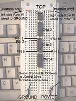
Setting up the breadboard
The Breadboard has two sides, which are electrically insulated from each other.We will call the left side GROUND and the right side POWER. We supply power and ground to the board by plugging our DC Power supply leads into bottom of the board (as shown). I recommend soldering these connections to pieces of (more rigid) jumper wire. You must match the positive wire from the power supply to the positive (right) side of the breadboard, and the negative lead to the left side. Usually, the positive wire will look different (e.g. have a white stripe like mine). The outermost holes on each side of the board are used to distribute power and ground (respectively) to an entire row of the board (I have wired the
first row to both power and ground sides in the photo below to illustrate this).
The chips have either 8 or 16 pins each. The pins are numbered counter-clockwise (from bottom left of chip) as shown.
Building
You may connect the power and ground connections from the DC power supply anytime but DON’T PLUG IN BOARD DURING ASSEMBLY!
Note: When putting on the chips exact row positions don’t really
matter, just as long as the chips go in the order specified and are "down
the middle" of board, with lettering READABLE FROM THE GROUND SIDE.
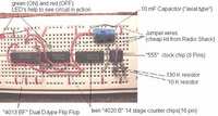
Install all the chips [refer to previous picture]:
Chip#1 is the 555 timer chip.
Chip#2 = 4020B counter chip.
Chip#3 = another 4020B chip.
Chip#4 = 4013BF dual D-type Flip Flop.
Note: We will only use one side of the "dual" F.F. I used a dual because it was available (and commonly found).
Wiring bottom chips
Note how pin8 on Chip#3 got its ground connection from a different row. You can get Power or Ground connections (respectively) from anywhere on the outer pin columns.
Note the optional LED’s. The green taps into pin1 on chip#4. This LED will show when the timer is ON (helps check things). The Green LED’s other leg plugs into the Ground (as shown). The Red LED will indicate when the timer is in the OFF state. It taps pin2 of Chip#4, and also needs to be grounded (as shown). NOTE: Make sure the LED’s you use have built in resistors, or else add a little resistance in series with each LED.
The Relay
Now that the logic portion of the timer is done. Go ahead and plug the DC Power supply block into the wall. The green and red LED’s should alternate 2 seconds green, 2 seconds red. This is the troubleshooting setting (we will adjust ON/OFF times later).
Connecting the relay:
The Solid State relay has two ends, the DC control end, and the AC power end. ***Caution*** AC current can kill you, so please be careful. Make sure the power strip is UNPLUGGED.
We begin by slicing through the outer plastic of the Power Strip’s insulation, about a foot or so from the plug. Peel back the insulation to reveal three wires (white, green, and black). The black one is the POWER wire, the one we will splice into the AC side of the relay. Cut the black wire and cut and peel back some insulation from each cut end. Make a small loop on each cut end, and screw down these loops under the relay’s screws (AC end). [See picture for details]
Connect two small (8-12") pieces of wire [see parts list] to the Relay’s DC
power and ground screws. Tape up the entire relay (especially the AC end) with black electrical tape (or duct tape). This will prevent any contact shorts and improve safety.
Plug in the Negative (black) and Positive (red) wires from the relay to where the GREEN LED was before (as shown). Note that I have soldered the ends of these wires to pieces of jumper wires (again, for more rigid connections).
Note that I have replaced two key wires from previous pictures with the YELLOW and GREEN wires (for clarity). Leave these wires connected at chip #4.
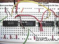
To Set ON/OFF times:
Chip #3 controls OFF time.
Chip #2 controls ON time.
To change these times, simply plug the Yellow or Green wires into other pins (on Chips 2 and 3) as follows:
The following times are valid for chip 2 (ON time) and chip 3 (OFF time):
|
Pin #
|
Schematic Pin
|
Delay Time
|
|
|
|
|
|
9
|
Q1
|
2 sec
|
|
7
|
Q4
|
16 sec
|
|
5
|
Q5
|
32 sec
|
|
4
|
Q6
|
~ 1 min
|
|
6
|
Q7
|
~2 min
|
|
13
|
Q8
|
~ 4 min
|
|
12
|
Q9
|
~ 8 min
|
|
14
|
Q10
|
~ 17 min
|
|
15
|
Q11
|
~34 min
|
|
1
|
Q12
|
~ 68 min
|
|
2
|
Q13
|
~ 2 hr 15 min
|
|
3
|
Q14
|
~4 hr 30 min
|
***Remember that the pins are numbered from 1-16 and arranged counter clockwise from bottom left of chip. Do not plug into any other pins besides those listed in table above!***
Sample time setting:
To set 64 sec. ON / 256 sec. OFF, plug the Yellow wire at chip #2 into pin#4, plug the Green wire at chip #3 into pin#13.
The board and relay could be fastened inside of a small plastic case with holes cut for the power strip cord ends. Make sure to keep components from touching though. Simply plug in your appliance into a spot on the power strip, plug in the strip and DC power supply, and set the ON/OFF times.
Here’s the schematic of the completed cyclestat.
Be sure to add a filter capacitor as the schematic indicates (not shown in photos) to ensure proper timer functioning.
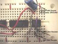
TIMER IMPROVEMENT
Below is the updated timer layout, featuring an "automatic on" function that restarts the timer in the ON position when power is applied. The resistance/capacitance values on the RC circuit are subject to what works. (The stated values worked for me, It’s all about resetting the chips for long enough time intervals when power up occurs — play around to find what works best for your timer.)
Shown Values:
Res. at bottom (added RC circuit) = 1K ohm
Res at middle = 10K ohm
Cap. at bottom (RC circuit) 68 uF.
|


 Button Ads!